

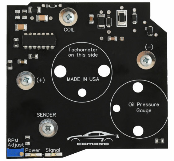
Tachometer Still Not Working After Replacing the Circuit Board?
If the tachometer still is not working after replacing the circuit board, the problem may be somewhere else in the system. This guide provides practical troubleshooting steps to help determine whether the problem is with the tachometer, vehicle wiring, power or ground, or the ignition signal.
Please Read This Section Carefully
The original tachometer circuit board is a common failure point on these 30+ year-old vehicles. In many cases, replacing the original board restores normal tachometer operation and is the correct repair.
Every replacement tachometer circuit board we ship is bench tested and calibrated on the day it is shipped. This confirms that the circuit board is operating properly before it leaves our facility.
If the tachometer still does not operate correctly after installation, the problem may be elsewhere in the tachometer system. Possible causes include a poor power or ground connection, damaged wiring, an incorrect or unstable tach signal, a defective tach filter, or a fault in the gauge movement itself.
More than one fault can also exist at the same time. For example, the original circuit board may have failed from age while a separate wiring, signal, ground, or gauge-movement problem is also present.
If your tachometer still does not operate correctly after installing the replacement circuit board, use the diagnostic steps below to help locate the remaining problem.
Quick Symptom Guide
| Symptom | Most Useful First Check |
|---|---|
| No tachometer movement | Verify power and ground, then verify the tach signal. |
| Partial or repeatably incorrect readings | Check the gauge movement and its connections. |
| Normal at low RPM but erratic at higher RPM | Check power, ground, wiring, tach filter, and HEI tach signal. |
| Occasional random jumping | Check for intermittent connections, wiring faults, or electrical noise. |
Start With the Basics: For most tachometer problems, verify power and ground first. Do not assume these circuits are good simply because other instruments in the cluster are working.
If the Tachometer Partially Works
If the tachometer moves only part of the scale, gives repeatably incorrect readings, or changes position incorrectly at certain RPM levels, the problem may be inside the gauge movement itself.
Some OEM tachometers use two internal windings and three terminals: two winding terminals and one common terminal. An open winding, poor terminal connection, or other internal fault can produce repeatable incorrect readings rather than a completely dead tachometer.
Application-Specific Example: The following observations apply to some 1982-1989 Camaro OEM tachometers with a 7000 RPM scale. Other OEM and aftermarket tachometers may behave differently.
Observed 1982-1989 Camaro Gauge-Movement Patterns
| Test RPM | Terminal One Open | Terminal Two Open | Common Terminal Open |
|---|---|---|---|
| 750 RPM | No needle movement | Approximately 2700 RPM | May return to 0 RPM |
| 3000 RPM | Approximately 3700 RPM | Approximately 2500 RPM | Approximately 5000 RPM |
| 5000 RPM | Full-scale, approximately 7000 RPM | Approximately 3700 RPM | Approximately 5000 RPM |
These patterns may help identify an open winding, poor terminal connection, or another fault within the gauge movement.
If the Tachometer Does Not Work at All
If the tachometer does not respond at all, work through the following checks in order.
Step 1 — Verify Power and Ground
Confirm that the tachometer has the correct power supply and a good ground.
Inspect for:
- Loose or corroded terminals
- Damaged or deteriorated wiring
- Poor crimps or splices
- Loose instrument-cluster connections
- Poor chassis or instrument-panel grounds
With the circuit powered, measure voltage directly between the tachometer power and ground connections. This verifies the voltage actually available to the tachometer through its normal power and ground circuits.
If a ground problem is suspected, perform a voltage-drop test between the tachometer ground and a known-good vehicle ground or battery negative while the circuit is operating.
Also perform a wiggle test on the power and ground wiring and connectors while watching the tachometer and meter readings.
Step 2 — Verify the Tachometer Signal
On a GM HEI ignition system, the tachometer signal is normally supplied by the TACH terminal on the distributor.
Inspect the signal circuit for:
- Loose or corroded terminals
- Damaged wiring
- Poor crimps or splices
- Loose connectors
If an oscilloscope is available, verify that a tach signal is present at the HEI TACH terminal and that its frequency changes as engine RPM changes.
Step 3 — Bypass the Tachometer Signal Filter
If a tachometer signal filter is installed, temporarily bypass it during testing.
A defective or incorrect filter can prevent the tachometer from receiving a usable signal.
Test Result: If the tachometer begins working with the filter bypassed, test or replace the filter before returning it to service.
Do not assume that an installed tach filter is good simply because it worked previously.
Step 4 — Try a Temporary Direct Tach Signal Wire
Run a temporary test wire directly from the HEI distributor TACH terminal to the tachometer signal input.
This bypasses the vehicle's original tach signal wiring, connectors, and splices. If a tach filter is normally installed, leave it bypassed during this test.
Route the temporary wire safely away from exhaust components, belts, fans, throttle linkage, spark plug wires, and other moving or high-temperature components.
Test Result: If the tachometer begins working with the temporary wire installed, inspect the original signal wiring, connectors, and tach filter.
Step 5 — Disconnect Other Devices From the Tach Signal
If other equipment is connected to the HEI TACH terminal or tach signal wire, temporarily disconnect it during troubleshooting.
Examples may include:
- Aftermarket ignition equipment
- EFI systems
- Cruise-control systems
- Shift lights
- RPM switches
- Aftermarket tachometers
- Other accessories using an RPM signal
Whenever practical, test the factory tachometer with only the required tach signal connection in place.
Step 6 — Test With a Known-Good Compatible Tachometer
If available, connect a known-good compatible tachometer to the same power, ground, and tach signal source.
If the known-good tachometer also does not operate: The problem is likely in the vehicle power, ground, wiring, or signal source.
If the known-good tachometer works normally: Further testing of the original tachometer assembly may be required.
Remember: Your replacement circuit board was bench tested and calibrated before shipment. If the tachometer still does not operate, verify the vehicle power, ground, tach signal, wiring, filter, and gauge movement before assuming the replacement circuit board is the cause.
If the Tachometer Jumps or Becomes Erratic at Higher RPM
A tachometer that operates normally at idle and lower engine speeds but begins to jump, fluctuate, or give erratic readings as RPM increases usually indicates a problem with the tachometer signal, wiring, power, or ground rather than the tachometer circuit board.
This condition is uncommon. Based on our customer support experience, it accounts for less than 1% of the tachometer problems reported to us.
On a GM HEI ignition system, the tachometer signal is supplied by the TACH terminal on the distributor. A problem with the signal or the wiring carrying that signal may become more noticeable as engine speed increases.
Typical Symptoms
- Tachometer operates normally at idle and lower RPM
- Needle begins to jump or fluctuate as RPM increases
- Needle occasionally moves above or below the actual engine RPM
- The problem occurs only above a particular RPM
- The amount of needle movement may increase as engine speed increases
Testing Procedure
1. Check Power and Ground
Begin by verifying the tachometer power and ground connections.
Inspect for loose or corroded terminals, poor crimps or splices, damaged wiring, loose printed-circuit or connector contacts, and poor instrument-panel grounds.
With the engine running, measure voltage directly between the tachometer power and ground connections. The voltage should remain reasonably stable as RPM increases through the range where the problem occurs.
If a ground problem is suspected, perform a voltage-drop test between the tachometer ground and a known-good vehicle ground or battery negative while the circuit is operating.
Perform a wiggle test on the power and ground wiring while watching the tachometer and meter readings.
2. Inspect and Wiggle-Test the Tach Signal Circuit
Inspect the wiring from the HEI distributor TACH terminal to the tachometer.
Look for:
- Loose or corroded terminals
- Poor crimps or splices
- Damaged wiring
- Loose connectors
- Signal wiring routed close to spark plug wires or other sources of ignition interference
Carefully perform a wiggle test on the signal wiring and connectors with the engine running. If moving the wiring causes the tachometer to become unstable, repair the affected connection or wiring.
3. Bypass the Tachometer Signal Filter
If a tachometer signal filter is installed, temporarily bypass it and operate the engine through the RPM range where the problem normally occurs.
Test Result: If the tachometer becomes stable with the filter bypassed, the filter should be tested or replaced.
Do not assume an installed filter is good simply because it has previously operated correctly.
4. Bypass the Vehicle Tach Signal Wiring
Run a temporary test wire directly from the HEI distributor TACH terminal to the tachometer signal input. Leave the tach signal filter bypassed during this test.
Operate the engine through the RPM range where the problem normally occurs.
Test Result: If the tachometer operates normally with the temporary wire installed, the problem is most likely in the original vehicle wiring, connectors, or tach filter.
Route the temporary wire safely away from moving parts, exhaust components, and spark plug wires.
5. Disconnect Other Devices From the Tach Signal
If another device is connected to the HEI TACH terminal or tach signal circuit, temporarily disconnect it and retest the tachometer.
An additional device or a fault in its wiring can load or interfere with the tach signal. Test the factory tachometer with only the required tach signal connection whenever practical.
6. Check the Tach Signal With an Oscilloscope
An oscilloscope is the best method of determining whether the tach signal becomes unstable as engine RPM increases.
First check the signal directly at the HEI distributor TACH terminal. Observe the waveform at idle and then increase engine speed through the RPM range where the tachometer normally becomes erratic.
The waveform should remain consistent and repetitive as engine speed increases. The frequency of the signal should increase smoothly with RPM.
Look for abnormalities that appear at the same time the tachometer becomes unstable, including:
- Missing or irregular ignition pulses
- Additional pulses that are not part of the normal repeating waveform
- Intermittent loss of the tach signal
- Random electrical noise superimposed on the normal signal
- A noticeable change in waveform consistency as RPM increases
Important: Some switching transients and ringing may normally be present on an HEI tach signal. The important consideration is whether the waveform remains consistent from one ignition event to the next. Random or additional disturbances may cause the tachometer to register false ignition events and produce a jumping needle.
If the waveform is stable at the HEI TACH terminal but becomes irregular at the tachometer input, inspect the vehicle wiring, connections, tach filter, and wire routing between the distributor and tachometer.
If abnormal signal activity is present directly at the HEI TACH terminal, further diagnosis of the ignition system and anything connected to the tach signal circuit may be required.
Oscilloscope Warning: Use an oscilloscope and probe suitable for automotive ignition-system testing. Do not assume that an ordinary low-voltage oscilloscope input can be connected directly to the HEI TACH terminal.
Why Signal Quality Matters
The tachometer circuit board determines engine RPM from the electrical pulses it receives from the HEI ignition system. If those pulses become irregular, contain additional pulses, or are intermittently lost, the tachometer may interpret them incorrectly and the needle may jump even though the tachometer circuit board is operating normally.
Before replacing or returning a tachometer circuit board for an erratic high-RPM indication: Remember that the board was bench tested and calibrated before shipment. Verify power and ground, inspect the wiring and connections, bypass the tach filter, perform the temporary direct-wire test, disconnect other equipment from the tach signal when applicable, and inspect the signal with an oscilloscope when possible.
If the Tachometer Jumps Occasionally
If the tachometer works normally most of the time but occasionally jumps or behaves erratically, begin by checking the power, ground, signal wiring, and connections for intermittent faults.
Things to Check
- Perform a visual inspection of the related wiring and connectors.
- Perform a wiggle test while watching the tachometer.
- Check for loose terminals, poor grounds, damaged wiring, or intermittent connections.
- Temporarily disconnect other equipment connected to the tach signal.
- If the electrical checks are satisfactory, consider electrical noise on the tach signal as a possible cause.
When a Tachometer Signal Filter May Help
In some cases, a tachometer signal filter may help reduce unwanted interference on the signal line.
A tach filter is not a universal fix. It should not be used to conceal a wiring, grounding, connection, or ignition-system problem.
You can also read our related article: How Tachometer Filters Work — Will It Work for My Application?
Final Notes
The original circuit board is a common failure point in these older tachometers, and replacing it is often the correct repair. Every replacement tachometer circuit board we ship is bench tested and calibrated on the day it ships to confirm proper operation before it leaves our facility.
If the tachometer still does not operate correctly after installation, another fault may be present elsewhere in the system.
Recommended Troubleshooting Order: Verify power and ground first. Then inspect the wiring and connections, verify the tach signal, bypass any filter when appropriate, and isolate the signal circuit before replacing additional components or returning the replacement circuit board.
If you need to check the tachometer needle’s resting position, also see: Calibrating the Tachometer Needle to the Zero Rest Position.